Content:
Introduction
1. Importance of Glass Edge Processing
1.1 Enhancing Safety
1.2 Inproving Structural and Aesthetic Quality
1.3 Inflluence on Subsequent Processing
1.4 Industy Standard and Guidelines
2. Type of Glass Edge
2.1 Safety Edge
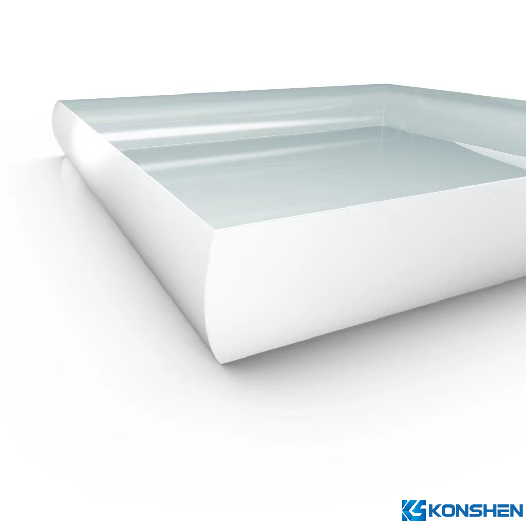
2.2 Round Edge(Pencil Edge)
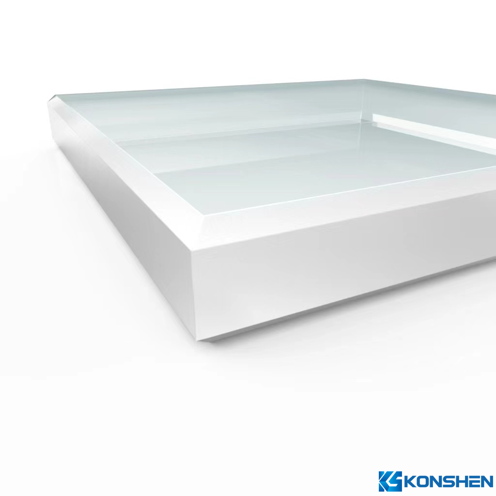
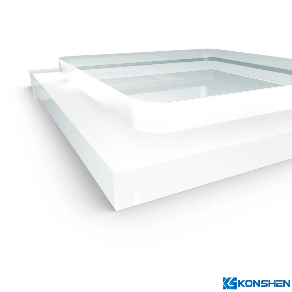
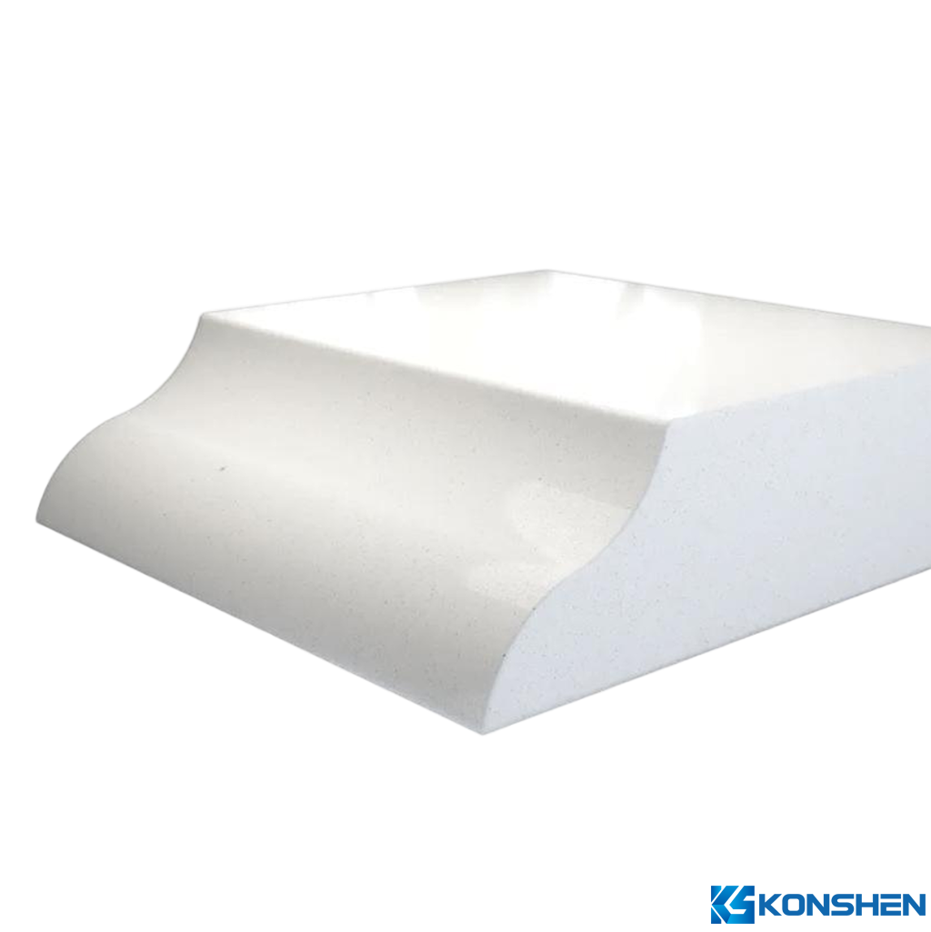
2.3 Step Edge
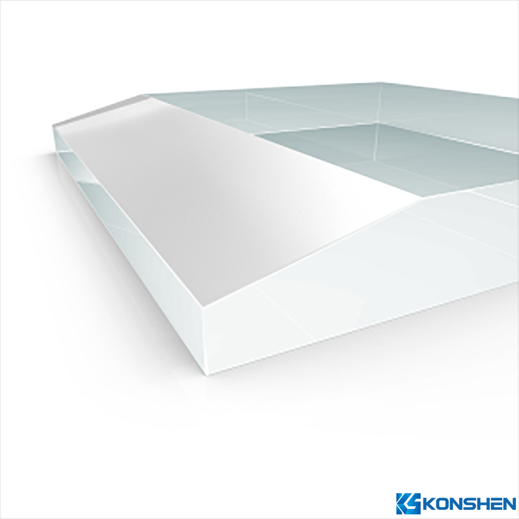
2.4 Beveled Edge
2.5 Ogee Edge
2.6 2.5D Edge
3. Type of Chamfering
3.1 Safety Corner
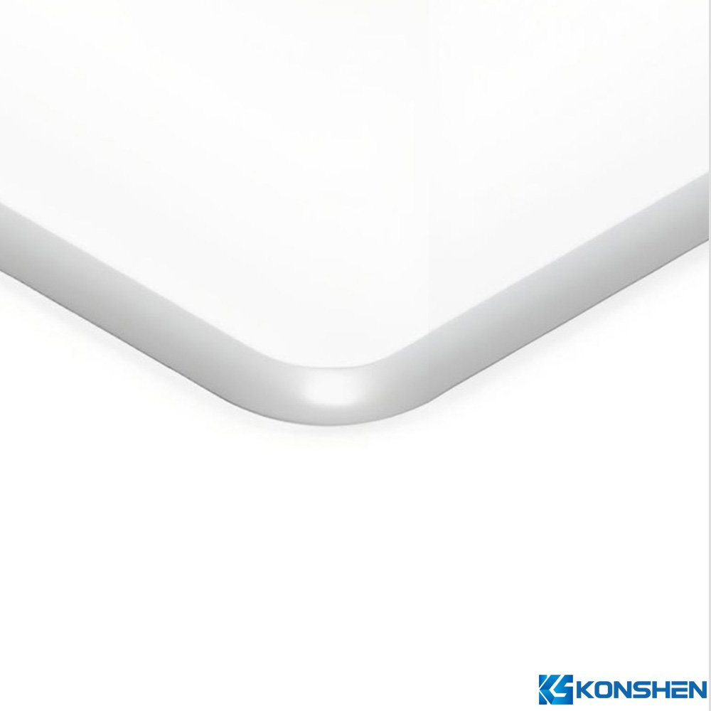
3.2 Radius Corner(R-Corners)
3.3 Cut Corner
3.4 Tolerence and Inspection
3.4.1 Dimensional Tolerance Control
3.4.2 Inspection Methods
3.4.3 Cost and Efficiency Factors
3.5 Process Standards and International Comparison
4.Glass Edge Processing Technology
4.1 Basic Working Principles
4.2 Tools and Equipment
4.2.1 CNC Machines
4.2.2 Precision Engraving Machines
4.2.3 Polishing Machines
4.3 Edge Process Combination Strategy
4.4 Processing Cycle and Efficiency Optimization
4.4.1 Cycle Time Control
4.4.2 Efficiency Strategies
4.4.3 Quality vs. Cost Balance
4.5 Environmental and Safety Control
5.Common Edge Defects and Solutions
5.1 Chipping
5.2 Microcracks
5.3 Uneven Chamfer
5.4 Poor Polishing / Haze
5.5 Corner Chipping & Edge Breakage
5.6 Quality Inspection and Verification
Conclusion
In the field of modern glass deep processing and manufacturing, edge treatment is a critical process that determines product quality and safety, following cutting. Whether applied in automotive, consumer electronics, industrial control, optical, or medical laboratory applications, glass edges play essential roles in structural support, safety protection, and aesthetics. Untreated glass edges often contain micro-cracks or chips that not only pose safety hazards but can also lead to breakage during tempering, printing, or transportation. This article systematically explores the technical system of glass edge processing—from edge types and chamfer forms to processing equipment, quality inspection, and application cases—to reveal the crucial yet often overlooked techniques that determine success in high-end glass processing.
The edges of glass are zones of stress concentration and are the main initiation points for crack propagation, making them the most fragile part of the material. The quality of edge processing directly determines mechanical strength and safety during use. Processed edges not only resist impact better but also reduce the risk of breakage during subsequent manufacturing and handling.
After cutting, glass edges often contain sharp corners and micro-cracks that can easily break under physical or thermal stress. Edge processing helps remove these defects and establish a stress buffer zone. For example, tempered glass typically offers 3–5 times the strength of ordinary glass, but only if edges are uniformly processed. If edge cracks remain, breaking stress may drop by more than 40%. Experiments show that a 3mm tempered glass sample with standard safety edges can withstand IK06 impact, whereas an untreated counterpart may break at IK03 or below.
Edge processing is key not only to safety but also to structural performance and appearance:
Uneven edges can negatively affect screen printing, coating uniformity, and lamination:
Screen Printing: Excessive roughness reduces ink coverage and adhesion.
Coating Quality: Edge particulates or chips may cause discharge during vacuum coating.
Bonding: Asymmetric chamfering can create stress concentration, leading to bubbles and delamination.
Thus, in high-precision applications such as AR/AF coatings or optical windows, edge finishing is designated as a Key Quality Control (KQC) point.
Glass edge processing requirements are governed by multiple standards:
Glass edge profiles determine not only safety and appearance but also assembly precision, sealing performance, and structural integrity. Common types include safety edge, step edge, round edge, ogee edge, 2.5D edge, and bevel edge.
These are small chamfers applied to the corners of rectangular glass to avoid sharp angles and protect handlers during assembly and transportation.
Typical radius: R0.5–R1.0mm
Machining method: diamond wheel or CNC finishing
Tolerance: ±0.05mm
Used extensively in consumer electronics and industrial control panels for better strength and aesthetics.
|
Type |
-Value Range |
Method |
Tolerance |
|
Small |
R0.3-R1.0mm |
CNC polishing/Manual Chamfering |
±0.03mm |
|
Medium |
R1.5-R3.0mm |
CNC + polishing |
±0.05mm |
|
Large |
R4.0mm + |
Custom fixtures |
±0.1mm |
Technical Description:
CNC chamfering is performed using diamond grinding wheels with coolant control.
The chamfer surface must remain continuous and smooth, without chatter marks.
Chamfer dimension tolerance affects assembly fit and must be clearly specified on the drawing.
A Cut Corner is a glass processing technique where the original 90° sharp corner of the glass is partially removed to form a flat chamfered segment or short beveled edge. This process effectively reduces stress concentration at the corner and improves structural clearance, assembly fit, and mechanical stability.
It is commonly used in applications where the glass needs to align precisely with clips, fasteners, or device housings. The process is typically performed using CNC machines, water jet cutting, or automatic chamfering machines, followed by edge finishing and polishing to ensure a smooth, defect-free surface.
Technical Parameters
Cutting Angle: Typically 45°, but can be customized according to design requirements
Corner Length: Usually ranges from 1mm to 20mm, depending on glass size and assembly requirements.
Machining Tolerance: Dimension tolerance controlled within ±0.1mm to ensure precise assembly fit.
Surface Roughness: Polished surface roughness can reach Ra ≤ 0.05μm, ensuring smooth edges.
The stability of chamfer dimensions directly affects the assembly precision and final yield of glass products.
Standardized dimension control can be achieved through the following measures:
Chamfer depth tolerance: ±0.05 mm
Chamfer width tolerance: ±0.1 mm
Chamfer angle deviation: ±1°
Corner radius (R) deviation: ±0.05 mm
High-precision optical measurement systems
Non-contact profilometers for angle and curvature detection
Optical interferometry to measure chamfer surface roughness
Key factors influencing chamfering costs include:
Grinding wheel grit size and lifespan
Equipment precision level
Processing speed and coolant flow
Workpiece fixture positioning accuracy
Cost Optimization Recommendations:
Use mechanical chamfering for non-visual areas
Apply CNC fine chamfering plus chemical polishing for high-end display zones
Standardize R-radius specifications in batch production to reduce tooling change frequency
| Item | China Standard | International Standard | Requirement Description |
|
Chamfer dimensions |
GB/T 15763.2-200 |
ASTM C1048-18 |
R-values or angles must be specified on drawings |
|
Chamfer surface quality |
GB/T 9963-2018 |
ISO 614 |
|
|
Chamfer angle deviation |
GB/T 28217-2018 |
EN 12150-2 |
±1° is the recommended tolerance |
|
Chamfer surface roughness |
GB/T 13822-2008 |
ISO 4287 |
Ra ≤ 0.02 μm for optical-grade quality |
With the rapid development of high-end manufacturing, clients now demand higher requirements for glass products—from dimensional tolerance and edge smoothness to impact resistance and uniform thermal stress distribution. Every indicator relies on precise edge processing. Modern edge processing has evolved from simple grinding to a comprehensive system integrating fully automated CNC grinding, chamfering, polishing, cleaning, and inspection.
Glass edge processing primarily removes excess material through grinding and polishing to achieve the specified geometry and surface roughness. Based on the purpose, it can be divided into Grinding, Chamfering, and Polishing stages.
1) Grinding Principle
Grinding uses high-hardness diamond particles on a wheel to remove material from the glass edge at high speed. The wheel speed typically ranges from 2800–4800 rpm. By controlling feed rate and pressure, micro-layer material removal is achieved.
Key Parameters:
|
Item |
Range/Parameter |
Technical Description |
|
Wheel grit |
#80–#400 |
Coarse grinding: #80–#180; Fine grinding: #240–#400 |
|
Grinding line speed |
20–40 m/s |
Too low causes edge chipping; too high increases thermal stress |
|
Feed rate |
200–600 mm/min |
Depends on glass thickness and material |
|
Coolant flow |
10–15 L/min |
Prevents thermal cracking and surface burn |
2)Chamfering Mechanism
Chamfering geometrically refines the glass edge by modifying the grinding wheel shape (V-type, R-type, bevel-type). It improves safety and ensures assembly edge consistency.
Chamfer angle range: 15°–45°
Chamfer width control: 0.5–3.0 mm
Typical equipment accuracy: ±0.05 mm
Sufficient cooling and wheel sharpness are critical to avoid corner chipping and uneven bevels.
3)Polishing Process
Polishing removes grinding micro-cracks and improves optical transparency and surface quality.
Common Methods:
Mechanical polishing: Using cerium oxide (CeO₂) or iron oxide powders
Chemical polishing: Surface chemical etching via acidic or alkaline solutions
Chemical-Mechanical Polishing (CMP): Combines mechanical and chemical action for high-optical glass
Technical Requirements:
Polishing speed: 300–1000 rpm
Polishing time: 60–300 s
Surface roughness (Ra): ≤0.02 μm (optical grade)
Micro-crack removal depth: ≥20 μm
CNC machines are the core of modern glass processing. They precisely control grinding paths for high consistency, accuracy, and complex edge shapes.
Technical Parameters:
Processing accuracy: ±0.02 mm
Repositioning accuracy: ±0.01 mm
Max processing size: 2500 × 1500 mm
Wheel speed: 3000–5000 rpm
Supported edge types: straight, R-corner, bevel, stepped, ogee
Advantages:
High precision and repeatability
Handles complex shapes
Automatic tool change and program control reduce manual intervention
Integrates with vision inspection for automated production lines
Limitations:
High equipment cost
Longer processing time
High requirements for environment cleanliness and cooling systems
Used for small, complex glass edges and microstructures. Higher spindle speed and flexibility make them ideal for small batch custom shapes.
Typical Parameters:
Spindle speed: 30,000–60,000 rpm
Accuracy: ±0.01 mm
Thickness range: 0.3–5 mm
Can achieve R-corner, bevel, irregular holes, and fine grooves
Advantages:
Small batch customization
Processes irregular geometries
High surface finish
Compatible with glass, sapphire, and ceramic
Limitations:
Limited processing area
Slower processing speed
High tool wear and cost
Used to remove micro-cracks, scratches, and hazed layers after grinding. Types: mechanical, chemical, or combined.
|
Type |
Principle |
Advantage |
Limitation |
|
Mechanical |
Physical friction |
Low cost, high efficiency |
Possible residual micro-cracks |
|
Chemical |
Surface chemical dissolution |
No mechanical stress, pure surface |
High cost, strict environmental requirements |
|
CMP |
Chemical + mechanical |
Best optical performance |
Complex process control |
Common Materials:
Polishing slurry: CeO₂ 5–15 wt%
Polishing pad: polyurethane, felt, or foam
Pressure: 0.05–0.2 MPa
Rate: 0.1–0.5 μm/min
Inspection Standards:
Surface Ra ≤ 0.02 μm
No visible scratches
Edge transmittance ≥ 90%
Common process combinations:
Standard for high-end displays, medical, industrial glass
Pros: High precision, uniform edges, smooth surface
Cons: Long cycle, high equipment requirements
2)Coarse Grinding + Fine Grinding + Mechanical Polishing
Suitable for building glass and home appliance panels
Pros: Cost-effective, efficient
Cons: Slightly higher surface roughness, for non-visual areas
3)CNC + Chemical Polishing
For optical-grade glass (camera modules, medical windows)
Pros: Mirror-finish edges
Cons: High cost, strict environmental compliance
Single-piece processing (CNC + Polishing): 90–180 s/piece
Multi-station linkage: down to 30 s/piece
Multi-axis linkage allows simultaneous grinding and chamfering
Optimize wheel grit progression (coarse → fine → polish)
Automatic tool change to reduce downtime
Online measurement to monitor dimensional deviation
Energy-saving cooling system reduces fluid consumption by >30%
| Process Route | Yield | Cost Index | Application |
| Coarse + Polishing | 90–92% | 1.0 | Building glass |
| CNC + Polishing | 96–98% | 2.3 | Industrial, display panels |
| CNC + Chemical Polishing | 98–99% | 3.0 | Medical optics |
Glass edge processing generates dust and wastewater.
Measures:
Enclosed processing chambers
Circulating coolant system
HEPA filtration for glass particles
Operators wear safety glasses and cut-resistant gloves
Edge defects arise from mechanical, thermal, and environmental factors. Identifying, analyzing, and optimizing processes is key for consistent quality.
Description: Local edge breakage or missing pieces
Causes:
Excess grinding pressure
coarse or dull wheel
insufficient coolant
mismatched feed
poor cutting quality
Standards:
GB/T 9963-2013, EN 12150-1:2015
Minor chipping depth ≤ 0.3 mm (mobile cover glass ≤ 0.1 mm)
Severe chipping length ≥ 1 mm = fail
Solutions:
Finer grit (#240+), reduce feed by 15–20%
Maintain coolant >12 L/min
Wheel dressing
Pre-cut allowance 1–2 mm
Description: Invisible fine stress cracks, depth 10–50 μm
Causes:
Excessive grinding pressure
Wheel wear
High coolant temperature
No post-grinding polishing
High internal stress
Detection:
Polarized stress
Microscopy (50–200×)
UV fluorescence
Standards:
GB 15763.2-2020, ASTM C158-02
Depth ≤30 μm (optical/medical), 40–50 μm (3C electronics)
Length ≤0.5 mm, no through-edge cracks
Solutions:
Add chemical polishing
Reduce contact pressure ≤0.15 MPa
Control coolant 18–25°C
Finer wheel (#320+)
Annealing for high-stress glass
Description: Inconsistent width or angle
Causes:
Wheel wear
Unstable fixture
Thickness tolerance
Unoptimized CNC path
Spindle wobble
Inspection:
GB/T 2828.1-2012, ISO 2768-mK
Width tolerance ±0.1 mm
Angle ±1°
Parallelism ≤0.05 mm
Solutions:
CNC dual-spindle
Laser measurement
Fixture calibration
Wheel dressing
Optimized G-code
Description: Hazy or dull edges, reduced transmittance
Causes:
Uneven slurry
Pad contamination
Low pressure (<0.05 MPa)
Insufficient polishing time
Residual deep scratches
Detection:
Gloss ≥90 GU
Ra ≤0.02 μm
Interferometer for waviness
Solutions:
Maintain CeO₂ 10±2 wt%
Replace pads
Increase pressure 0.08–0.12 MPa
Polish 120–180 s
Ultrasonic cleaning
Description: Local corner breakage due to uneven chamfering or impact during transport
Causes:
No safety chamfer
Insufficient cushioning
Small processing allowance
Thermal shock in tempering/annealing
Standards:
EN 12150, GB/T 15763
Corner defect ≤1 mm acceptable
Crack depth >2 mm fail
Solutions:
Safety corner (R=0.5–1 mm)
Cushioning and vacuum fixtures
Thermal stress equalization
CNC micro-rounding
Pre-shipment edge testing
Inspection Items:
|
Content |
Method |
Equipment |
Tolerance/Standard |
|
Dimensional accuracy |
Digital caliper / CMM |
Coordinate measuring machine |
±0.02 mm |
|
Chamfer angle |
Optical gage |
Laser angle meter |
±1° |
|
Chipping |
Visual + microscope |
50× microscope |
≤0.3 mm |
|
Microcracks |
Polarimeter |
Strain viewer |
Depth ≤30 μm |
|
Polishing gloss |
Gloss meter |
Gloss Meter |
≥90 GU |
|
Edge stress |
Stress tester |
Polarimeter |
≤ 40 MPa |
Standards: GB/T 9963-2013, GB/T 15763.2-2020, EN 12150-1:2015, ASTM C158-02, ISO 1288-3:2016
Inspection Strategy: Batch sampling (ISO 2859-1, AQL 0.65), SPC monitoring, optical scanning for 30% efficiency improvement.
Glass edge processing is critical for safety, structural strength, aesthetics, and compatibility with downstream assembly. By selecting proper edge types and chamfering methods, combined with CNC grinding, precision engraving, and polishing, chipping, microcracks, and haze can be effectively controlled.Different applications—consumer electronics, industrial equipment, medical devices, and architectural glass—have varying requirements for edge precision, optical performance, and stress management, but the core goal remains: ensuring high reliability, consistency, and premium appearance of glass products to provide a solid foundation for assembly and use.
Ready to take your glass project to the next level? Contact us today to discuss your custom glass needs and get a quote!
contact us